Feeds:
Posts
Comments

Archive for the ‘Technique’ Category

Definition:

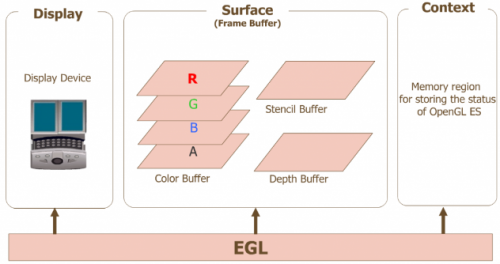
EGL is an interface between Khronos rendering APIs such as OpenGL ES or OpenVG and the underlying native platform window system.

It mainly handles the following tasks in Graphics System:

  • Graphics context management
  • surface/buffer binding
  • rendering synchronization
  • enabling “high performance, accelerated, mixed-mode 2D and 3D rendering using Khronos APIs”

EGL replaces GLX/AGL/WGL with a platform independent implementation.

Procedures to use EGL to render:

  1. Get EGLDisplay Object
  2. Initialize the connection with EGLDisplay Object
  3. Get EGLConfig Object
  4. Create EGLContext instance
  5. Create EGLSurface instance
  6. Connect EGLContext and EGLSurface
  7. Use GL command to render
  8. Disconnect and release EGLSurface connected with EGLContext
  9. Delete EGLSurface
  10. Delete EGLContext
  11. Disconnect EGLDisplay

Read Full Post »

Double Buffering

Computer Graphics Double Buffering

In Computer Graphics, double buffering is a technique for drawing graphics that shows no flicker/tearing, etc.

To update a page of text, it is much easier to clear the entire page and then draw the letter than to somehow erase all the pixels that are not in both the old and new letters. However, this intermediate image is seen by the user as flickering. In addition, computer monitor redraw the visible video page, so even a perfect update should be visible momentarily as a horizontal divider between the new image and the old image, known as tearing.

A software implementation of double buffering has all drawing operations store their results in some region of system RAM.and such region is called a back buffer.

When all drawing operations are considered complete, the whole region is copied into the video RAM(called front buffer).

This copying is usually synchronized with the monitor’s raster beam in order to avoid tearing. Double buffering necessarily requires more video memory and CPU times

for the date copying.

Page Flipping

Instead of copying the data, both buffers are capable of being displayed(both allocated in Video RAM). At any one time, one buffer is being displayed and the other is being drawn.

When drawing is completed, the roles of the two buffer are switched.

Page flipping is much faster than copying the data and can guarantee that tearing will not be seen as long as the pages flipping during the monitor’s vertical blank period when no video data

is being drawn. The currently active buffer is called front buffer and the background page is called the back buffer.

Read Full Post »

Protected mode

Definition:

80386+ provides many new features to overcome the deficiencies of 8086 which has almost no support for memory protection, virtual memory, multitasking or memory about 640K and still remain compatible with the 8086 family. The 386 has all the features of the 8086 and 286, with many enhancements. As in the earlier processors, there is the real mode, like 286, 386 can operate in protected mode, however, the protected mode on 386 is vastly different internally.Protected mode is not to protect your program, instead, it is to protect everyone else from your program.

Addressing:

Protected mode and real mode don’t seem to be very different. They all use memory segmentation, interrupts and device drivers to handle the hardware.

Real mode addressing

Memory is organized by 64K segments at least 16 bytes apart. Segmentation is handled through the use of an internal mechanism in conjunction with segment registers.

The contents of these segment registers(CS, DS, SS…) form part of the physical address that the CPU places on the bus address. The physical address is generated by multiplying the segment register by 16 and then add 16 bit offset. It is this 16 bit offset that limits us to 64K segments.


Protected Mode addressing

Segmentation is defined via a set of tables called descriptor tables.The segment registers contain pointers into these tables, there are two types of tables used to define memory segmentation:

GDT(Global Descriptor Table) and LDT(Local Descriptor Table).

The GDT contains the basic descriptors that all applications can access. In real mode, one segment is 64K big followed by the next in a 16 byte distance. In protected mode, we can have a segment as big as 4Gb and we can put it wherever we want. The LDT contains segmentation information specific to a task or program.

As OS could set up a GDT with its system descriptors and for each task an LDT with appropriate descriptors. Each descriptor is 8 bytes long. The format shows as the following figure:

Each time a segment register is loaded, the base address is fetched from the appropriate table entry. The contents of the descriptor is stored in a programmer invisible register called shadow registers so that future references to the same segment can use this information instead of reference the table each time. The physical address is formed by adding the 16 or 32 bit offsets to the base address in the shadow register.

We also have another table called interrupt descriptor table or the IDT. The IDT contains the interrupt descriptors. These are used to tell the processor where to find the interrupt handler.

Read Full Post »

CPU Modes

CPU modes are operating mode for the CPU of some computer architecture that places restrictions on the type and scope of operations that can be performed by certain processes being run by the CPU. This design allows the OS to run with more privileges than application software.


system calls which need switch between user and kernel space take time and can hurt the performance of a computing system,it is not common to allow time-critical software to run with full kernel privileges.

Any CPU architecture supporting protected execution will offer two distinct operating mode:

  1. Kernel mode (ring 0)
  2. User mode (ring 3)

The hardware is aware of the current ring of the executing instruction thread at all time, thanks to special machine register.

The purpose of distinct operating modes for the CPU is to provide hardware protection against accidental or deliberate corruption of the system environment by software.

Only “trusted” portions of system software are allowed to execute in the unrestricted environment of kernel mode.

All other software executes in one or more user modes.

Microkernel OS attempt to minimize the amount of code running in privileged mode.

Read Full Post »

ProcCreateWindow

ProcCreateWindow() extracts the fields of the xCreateWindowReq request sent by the client to use them as arguments for a CreateWindow() call:

pWin = CreateWindow(stuff->wid, pParent, stuff->x, stuff->y, stuff->width, stuff->height, …, (XID *)&stuff[1], …) (more…)

Read Full Post »

GART

GART — From DRI wiki

PCIe&AGP graphics hardware is dedicated high-speed bus that allow the graphics controller to fetch large amount of data directly from system memory. It uses a Graphics Address Re-mapping Table to provide a physical-contiguous view of scattered pages in system memory for DMA transfers.

Main memory is specifically used for advanced three-dimensional features, such as textures, alpha buffers …

There are two primary usage models for PCIe&AGP:

  • DMA ::: In the DMA model, the primary graphics memory is the local memory associated with the accelerator, referred to as the local frame buffer. 3D structures are stored in system memory, but are not used (or executed) directly from this memory; rather they are copied to primary (local) memory (the DMA operation) to which the rendering engine’s address generator makes its references. This implies that the traffic on the AGP tends to be long, sequential transfers, serving the purpose of bulk data transport from system memory to primary graphics (local) memory. This sort of access model is amenable to a linked list of physical addresses provided by software (similar to the operation of a disk or network I/O device), and is generally not sensitive to a non-contiguous view of the memory space.
  • execute ::: In the execute model, the accelerator uses both the local memory and the system memory as primary graphics memory. From the accelerator’s perspective, the two memory systems are logically equivalent; any data structure may be allocated in either memory, with performance optimization as the only criterion for selection. In general, structures in system memory space are not copied into the local memory prior to use by the accelerator, but are executed in place. This implies that the traffic on the AGP tends to be short, random accesses, which are not amenable to an access model based on software resolved lists of physical addresses. Because the accelerator generates direct references into system memory, a contiguous view of that space is essential; however, since system memory is dynamically allocated in random 4K pages, it is necessary in the execute model to provide an address mapping mechanism that maps random 4K pages into a single contiguous, physical address space

(more…)

Read Full Post »

VGA arbiter

Definition:

When multiple video cards are uncoordinatedly using the legacy VGA interface, one card might decode messages that were not sent to it.To solve this problem, it is needed an entity that controls all the accesses made using the legacy VGA interface. In Xorg this happens when multiple instances are running. It is important to note that some GPUs can skip completely if they are able to disable their VGA decoding resource.

(more…)

Read Full Post »

  • Verify with ATI tools

fglrxinfo:

$ fglrxinfo display: :0.0 screen: 0 OpenGL vendor string: ATI Technologies Inc. OpenGL renderer string: Radeon X1600 Series OpenGL version string: 2.1.7415 Release

if the vendor string is mesa, the driver wouldn’t configure properly the /etc/X11/xorg.conf

  • Verify with Linux Tools

glxinfo:

This command line option should report “direct” rendering

Xorg.0.log:

X server log file also contains useful info about driver installation.

  • Configuring

aticonfig:

aticonfig –initial (creates device section using fglrx)

aticonfig –overlay-type=Xv (Enable Video acceleration Xv Overlay)


Read Full Post »

Linux process segment layout

Read Full Post »

Arch Motherboard

To start off let’s take a look at how an computer is wired up nowadays:
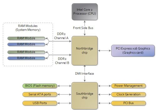
There are three main ways by which the CPU and the outside communicate: memory address space, I/O address space, and interrupts.

In a motherboard the CPU’s gateway to the world is the front-side bus connecting it to the northbridge. Whenever the CPU needs to read or write memory it does so via this bus. It uses some pins to transmit the physical memory address it wants to write or read, while other pins send the value to be written or receive the value being read.

Now comes the rub. We’re used to thinking of memory only in terms of RAM, the stuff programs read from and write to all the time. And indeed most of the memory requests from the processor are routed to RAM modules by the northbridge. But not all of them. Physical memory addresses are also used for communication with assorted devices on the motherboard.These devices include video cards, most PCI cards (say, a scanner or SCSI card), and also the flash memory that stores the BIOS

When the northbridge receives a physical memory request it decides where to route it: should it go to RAM? Video card maybe? This routing is decided via the memory address map. For each region of physical memory addresses, the memory map knows the device that owns that region. The bulk of the addresses are mapped to RAM, but when they aren’t the memory map tells the chipset which device should service requests for those addresses. This mapping of memory addresses away from RAM modules causes the classic hole in PC memory between 640KB and 1MB. A bigger hole arises when memory addresses are reserved for video cards and PCI devices. This is why 32-bit OSes have problems using 5 Gigs of RAM. In Linux the file /proc/iomem neatly lists these address range mappings. The diagram below shows a typical memory map for the first 4 gigs of physical memory addresses in a PC.

Actual addresses and ranges depend on the specific motherboard and devices present in the computer, but most Core 2 systems are pretty close to the above. All of the brown regions are mapped away from RAM. Remember that these are physical addresses that are used on the motherboard buses. Inside the CPU (for example, in the programs we run and write), the memory addresses are logical and they must be translated by the CPU into a physical address before memory is accessed on the bus.

The rules for translation of logical addresses into physical addresses are complex and they depend on the mode in which the CPU is running (real mode, 32-bit protected mode, and 64-bit protected mode). Regardless of the translation mechanism, the CPU mode determines how much physical memory can be accessed. For example, if the CPU is running in 32-bit mode, then it is only capable of physically addressing 4 GB (well, there is an exception called physical address extension, but ignore it for now). Since the top 1 GB or so of physical addresses are mapped to motherboard devices the CPU can effectively use only ~3 GB of RAM (sometimes less – I have a Vista machine where only 2.4 GB are usable). If the CPU is in real mode, then it can only address 1 megabyte of physical RAM (this is the only mode early Intel processors were capable of). On the other hand, a CPU running in 64-bit mode can physically access 64GB (few chipsets support that much RAM though). In 64-bit mode it is possible to use physical addresses above the total RAM in the system to access the RAM regions that correspond to physical addresses stolen by motherboard devices. This is called reclaiming memory and it’s done with help from the chipset.

That’s all the memory we need for the next post, which describes the boot process from power up until the boot loader is about to jump into the kernel. If you’d like to learn more about this stuff, I highly recommend the Intel manuals. I’m big into primary sources overall, but the Intel manuals in particular are well written and accurate.

Read Full Post »
Older Posts »